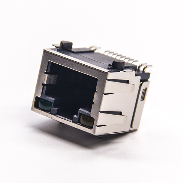
Network transformer and RJ45 wiring method

The wiring method between the network transformer and RJ45 usually follows the following steps:
1. **Understand the pins of the network transformer**: RJ45 network transformers usually have multiple pins, including RX (receive), TX (transmit), RX- (receive negative), TX- (transmit negative), etc. These pins need to be connected to the specific pins of the RJ45 interface.
2. **Confirm the pins of the RJ45 interface**: The RJ45 interface usually has 8 pins, of which pins 1, 2, 3, and 6 are used for data signals, pins 4 and 5 are usually used for grounding and unused, and pins 7 and 8 are often used for power and conflict warnings.
3. **Standard wiring method**: According to the 802.3 standard, pin 1 of RJ45 is connected to the RX of the network transformer, pin 2 is connected to RX-, pin 3 is connected to the TX of the network transformer, and pin 6 is connected to TX-. This wiring method is suitable for most Ethernet devices.
4. **Cross-cable wiring method**: If the devices at both ends support MDI/MDIX adaptation, the cross-cable wiring method can be used. In this way, pin 1 of RJ45 is connected to TX of the network transformer, pin 2 is connected to TX-, pin 3 is connected to RX, and pin 6 is connected to RX-.
5. **BOB-Smith circuit**: Pins 4, 5, 7, and 8 of RJ45 are usually connected to a 1000PF high-voltage capacitor through a 75-ohm resistor to form a BOB-Smith circuit to improve electromagnetic compatibility.
6. **Impedance matching**: Network transformers are also used to achieve impedance matching to reduce signal reflection and loss and ensure effective signal transmission. 7. **Protection isolation**: The protection isolation function provided by the network transformer can protect the connected devices from external interference and voltage surges, such as lightning strikes. When wiring, ensure that the pins of the network transformer are correctly connected to the corresponding pins of the RJ45 interface and follow the appropriate line sequence. Correct wiring is the key to ensuring stable communication between Ethernet devices. When designing the circuit, the selection of the network transformer and the circuit layout should also be considered to ensure optimal performance and reliability.


